Abstract
- Stands for General Purpose Input/Output
General Purpose
These pins are not dedicated to a single function. They can be configured flexibly as inputs or outputs, making them versatile for various projects
Input
GPIO pins can read signals from sensors, buttons, and other devices, providing data and feedback
Output
GPIO pins can send signals to control components like LEDs, motors, displays, etc. This powers interaction with the physical world
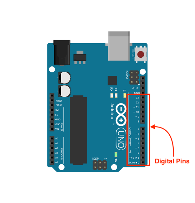
Digital Pin
- Can be used as input or output
- Input: Read digital values like the state of a button (HIGH for pressed, LOW for not pressed)
- Output: Send digital signals (HIGH for 5V, LOW for 0V) to control things like LEDs, small motors, relays, etc.
Arduino Uno
14 digital pins, labeled 0 to 13
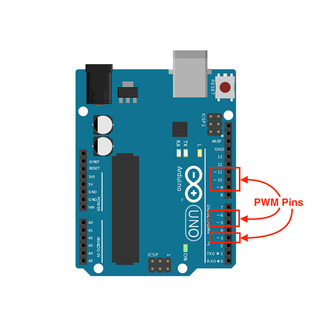
PWM (Pulse Width Modulation)
- Some Digital Pin (usually marked with a ’~’) have PWM functionality. This allows you to simulate analog output values for tasks like dimming LEDs or controlling motor speed
Arduino Uno
6 PWN pins, digital pin 3, 5, 6, 9, 10 and 11
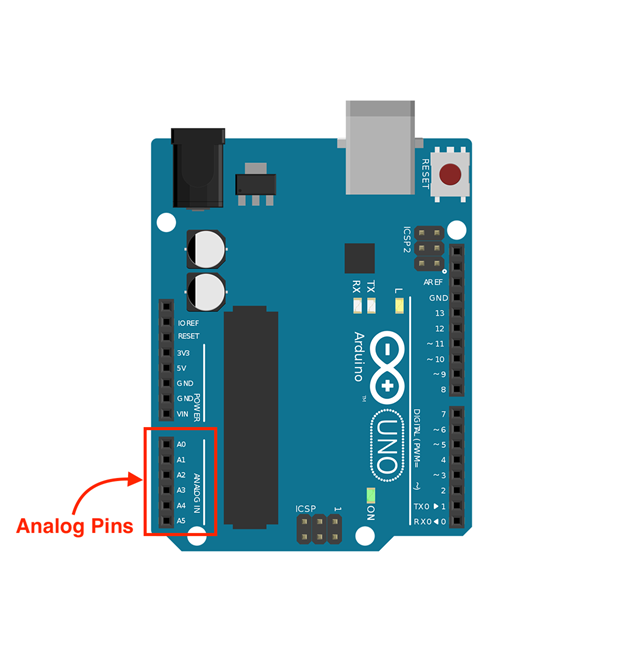
Analog Pins
- Used as inputs to read values from analog sensors (light sensors, potentiometers, temperature sensors, etc.)
- convert an incoming analog voltage (0-5V) into a digital value (0-1023)
Arduino Uno
6 analog pins, labeled A0 to A5
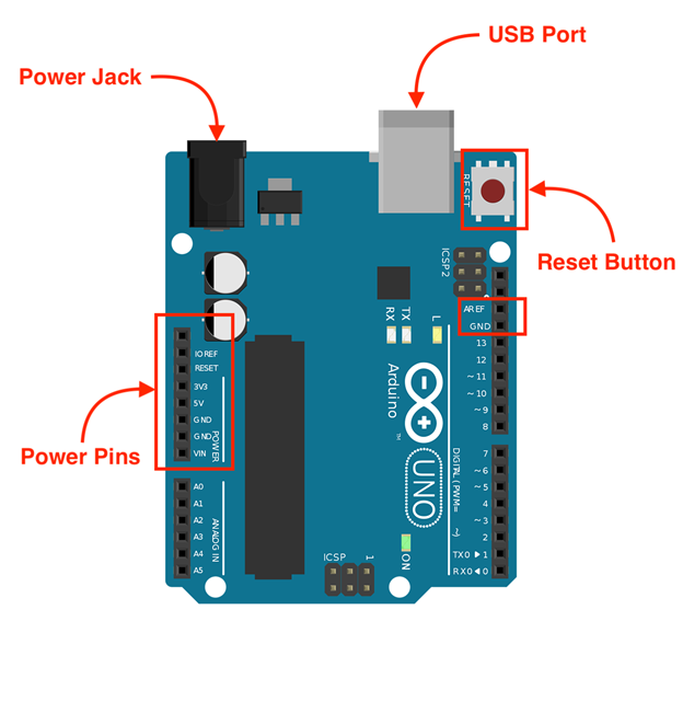
Power Pins
- 5V: Provides a 5-volt output.
- 3.3V: Provides a 3.3-volt output.
- GND (Ground): Common reference point for circuits. Multiple GND pins are available.
- VIN: Used to power the board like Arduino with an external power supply voltage (typically 7-12V)
Arduino Uno
Special Function Pins
- TX/RX: Transmit (TX) and receive (RX) serial data. Used for communication with the computer over USB or with other serial devices.
- AREF: Provides a reference voltage for analog inputs.
- Reset: Used to reset the Arduino board.
- I2C Pins (SDA/SCL): Used for communication with I2C devices (some sensors, displays, etc.)
- SPI Pins (MISO/MOSI/SCK): Used for communication with SPI devices (SD card modules, certain displays, etc.)


